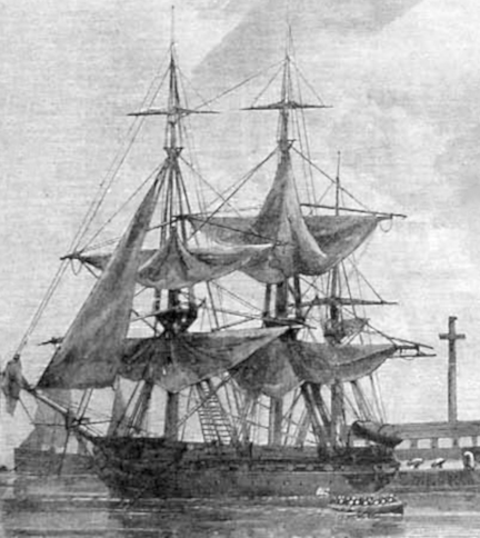
Drawing of the Vandalia of 1828.
Following is some general information about the vessel.
To go directly to information about the model, click here.
The (first) Vandalia of 1828 was one of a class of "Sloops of War" designed by a committee, which although it included illustrious ship designer Samuel Humphfreys, came up with a design that was ultimately a failure, at least for intended purposes. The Vandalia was one of the sloops of the "Boston" class. Sister ships included "Vincennes", "Concord", "Farifield", and "John Adams". All were rated as 18 gun sloops of war. After the War of 1812, in which the American frigates, particularly the heavy frigate Constitution and the 12-pounder 32 gun Essex performed admirably, the Navy Department decided not to build many more such ships nor to improve upon the design and performance of those vessels, but rather to create a class of small, fast ships which could operate in shallow coastal waters and rivers. Accordingly, the sloop-of-war design was the basis for a new class of ships, to be rated at 24 guns. Normally, a sloop of war is a fast, agile, lightly armed, ship-rigged vessel, smaller than a frigate, with a single open deck, which depends greatly on speed for its function and for protection.
There were several problems with the instructions and constraints given to the design committee. First, recent improvements in the manufacture of cannon allowed American foundry operators to cast larger guns and the Navy wanted to use these new 24-pounder long guns in this new class of sloops. Second, although the design of the class was supposed to be standardized, the politics of the day required that the construction of the members of the class be distributed among the various ship yards in the United States at that time. The Navy Board initially had approved Samual Humphreys' original design which included a fully round stern, and stipulated the ships should have 24 gun ports, not including bridle ports and ports in the stern. The Board, however, also added quarter galleries to the round stern. Furthermore, in the tradition of that time, each shipyard was permitted to make modifications to the design as long as the fundamental dimensions of the vessel remained similar to the original design. Once the preliminary plans reached the shipyards, there quickly evolved three different plans for the "standardized" design. One, by Doughty, was similar to the original but a with a slightly narrower hull and fuller ends. And a second, by Barker, eliminated the quarter galleries and restored the fully round stern. And, in a final blow to standardization, the captain assigned to each vessel, and his sailing master, were allowed to make design changes to suit their individual preferences.In American, English, and continental sailing ships up to the late 18th century, the flat transom across the stern was a weak spot in the hull, both in terms of structural integrity and in terms of poorer resistance to gunfire. By elimating the straight across timbers of a flat transom and substituting slanting or cant frames, similar to those used in the bow of the ship, later shipwrights evolved a fully rounded stern, which was stronger and soon became the industry standard for most sailing ships. The design committee apparently was of differing opinion about the "modern" rounded transom and came up with a compromise design, using cant frame for about the first half of the stern and finishing up with a somewhat more traditional transom, albeit one much narrower because the cant frames had decreased the width to be spanned. Another area of problem with the design was armament. The design committee originally planned the ships for twenty-four 24 pounder long guns on a single open deck. After the ships were launched, it became clear the hull could not carry the weight of the battery. The added weight made the ships float much lower in the water, and that drastically decreased the speed and maneuverability of the ships. Over all, the ships were soon regarded as slow and handling poorly in open water, not desirable in a "sloop". Armament was eventually reduced to 20 guns, eighteen 32 pounder carronades and two 32 pounder long guns, and the ships were re-rated as 18 guns.
There were ten sloops originally authorized.
Seven, "Boston" (1825 - Boston Navy Yard), "Vandalia" (1828 - Philadelphia Navy Yard), "Vincennes" (1826 - New York Navy Yard), "Concord" (1828 - Boston Navy Yard), "Fairfield" (1826 - New York Navy Yard), and "John Adams" (1829 - Boston Navy Yard) were built to the Humphreys plan, and make up the "Boston class".
Three, "Lexington" (1825 - New York Navy Yard), "Warren" (1825 - Boston Navy Yard), and "Natchez" (1827 - Norfolk Navy Yard) were built to the Doughty plan.
And one, "Falmouth (1827 - Boston Navy Yard) was constructed to Barker's plan.
The Vandalia was laid down in 1825 and launched and was commissioned in 1828. Built at the Philadelphia Naval Shipyard she was named for the Illinois city of Vandalia.
Specifications:
Length: 127 feet
Beam: 34.5 feet
Draft: 16.5 feet
Weight: 614 long tons.
With all the problems of the class of sloops, Vandalia herself had a remarkable history. After launch in 1828, she served with the Brazil Squadron in the south Atlantic intil 1831. In 1832, she was re-commissioned and assigned to the West Indies Squadron. De-commissioned for major repairs in 1834, she returned to the West Indies Squadron in January 1835 and served with that Squadron until 1838, during that time participating in the Seminole Indian Wars in Florida, in protecting American interests in the West Indies, and in suppressing the slave trade. She was in the Caribbean for a year, being de-commissioned again in 1839.
Vandalia was re-commissioned in 1842 and assigned to the Home Squadron, which performed routine patrol and reconnaissance duties as far north as Newfoundland and as far south as the mouth of the Amazon River. In 1845, after yellow fever broke out in the crew, Vandalia returned to Norfolk, and was decommissioned and laid up. During this time in ordinary which lasted until 1849, she was lengthened by 13 feet in 1848, and was re-armed with four eight inch shell guns and sixteen 32 pounder long guns. At least that was the official story. Some evidence suggests, however, that the Naval Department engaged in a bit of subterfuge. As with the Constellation, (see History of the Constellation on Constitution Page budget limitations did not permit building new ships, so the Vandalia, like the Constellation, was decommissioned for "repairs" and was, in essence, scrapped and replaced by an entirely different vessel bearing the same name. To the Naval accountants, I guess a ship was a ship and there must have been little attention paid to the actual dimensions of the "repaired" Vandalia, which was longer than the original. However it happened these changes improved the ship's performance as well as her fighting capability. The Vandalia was recommissioned on 9 August 1849 and joined the Pacific Squadron. She made several visits to the Hawaiian Islands in 1851 before returning to the New York Navy Yard on 6 October 1852 and going out of commission again.
In 1853, the ship joined Commodore Matthew C. Perry's East Indies Squadron. She was present at Commodore Perry's historic entrance into Tokyo Bay in 1854 and in 1855 helped to protect American interests in China during the Taiping Rebellion. Decommissioned at the Portsmouth (N.H.) Navy Yard in 1856 she was recommissioned in 1857 and assigned to the Pacific Squadron. In 1859, the warship rescued survivors of the American clipper ship Wild Wave, wrecked off Oeno and Pitcairn Islands, and conducted an expedition against natives at Waya, Fiji Islands, following the murder of two American citizens there. Vandalia returned to the New York Navy Yard early in 1860 and was decommissioned, but was recommissioned later the same year and assigned to duty with the East Indies Squadron.
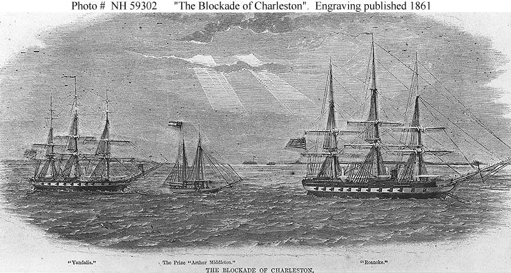
With the outbreak of the Civil War in April 1861, Vandalia was called back home and assigned to the South Atlantic Blockading Squadron. She served blockade duty off Charleston and Bull's Bay, S.C. and captured the schooner Henry Middleton in August and assisted in the capture of the sailing ship Thomas Watson in October of that year. The vessel also participated in the successful amphibious assault upon Roanoke Island, N.C., which operation closed the supply lines to Confederate-held Norfolk Navy Yard and was largely responsible for the evacuation of that vital naval facility six months later. Vandalia put into New York on 24 November to deliver the officers and crew of the wrecked steamer Governor.
Vandalia returned to duty with the South Atlantic Blockading Squadron and was deployed at multiple locations along the coast of South Carolina and Georgia. In December, 1862 the vessel was ordered north for major structural repairs at New York Navy Yard, and was decommissioned there before sailing to Portsmouth Navy Yard (N.H.) to serve as a receiving and guard ship. She remained there and was broken up sometime between 1870 and 1872. Overall, a remarkably long service for a wooden ship.
Drawing of the Vandalia of 1828.
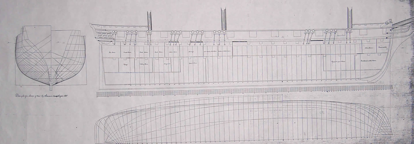
Photo of the plan of the sloop Vandalia from the National Archives.
My interest in this vessel began when I happened upon the Humphreys plan for the class of sloops while searching the collection of ship plans in the National Archives in College Park, MD. I was looking for a ship to model, and after I did a little research on the Vandalia I was interested enough to build a model. The plan was pretty detailed and showed the transitional half-round stern timbering and the curious quarter galleries. The draft of the lines was also signed by Samuel Humphreys and dated 1825. These last details were enough to get me started on researching the ship. For those interested, Howard Chapelle has some commentary on this class of vessel in his book "The History of the American Sailing Navy", c.1949 by W.W.Norton, reprinted by Bonanza Books, NYC.
Once I had photo-reduced the plan to the 1:64 scale I wanted to work in, I set about making the frames working directly from the hull lines on the plan. Because the plans also had an "inboard profile" showing the location of the various decks and rooms in the hull, I thought I might finish the interior of the ship, much as I had with the Essex, so I made the space between frames a bit larger than the plan stipulated to make the inside more visible. In retrospect, this was a mistake. I think it always better to err on the side of accuracy, and since the folks who made the hull plans provided so much information about the framing, it seems disrespectful not to abide by the plan, when an original is available. The inboard profile plan is also particularly interesting because of the contemporaneous notes and possible changes noted on the plan, also signed by Humphreys.
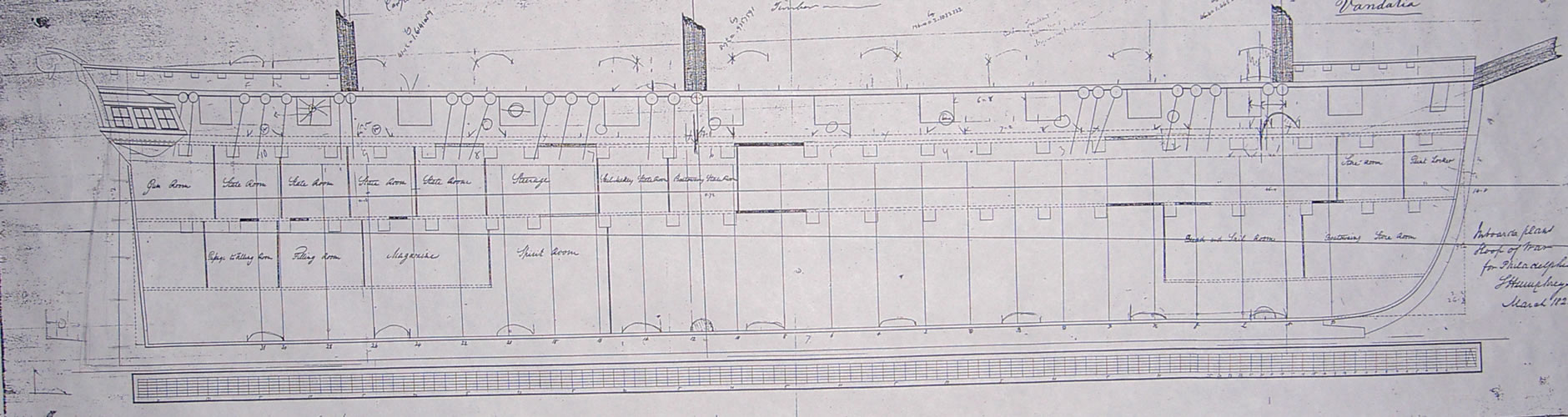
Photo of the plan of the sloop Vandalia from the National Archives.
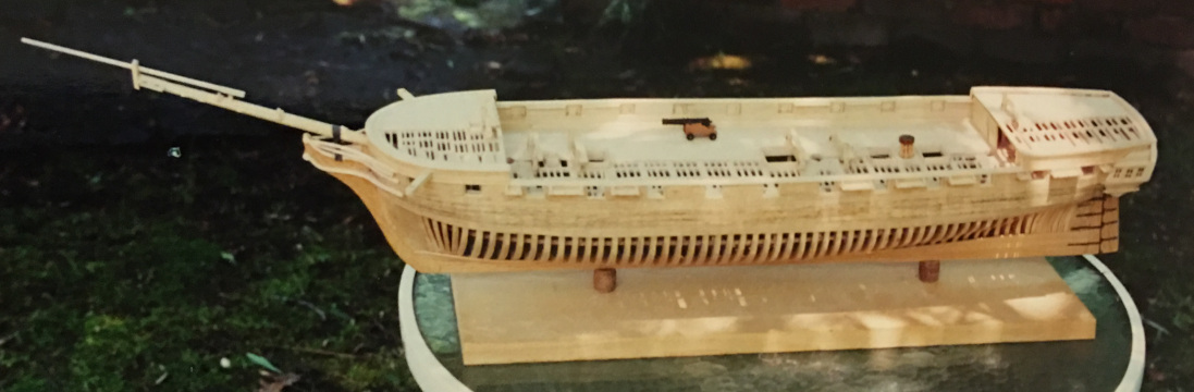
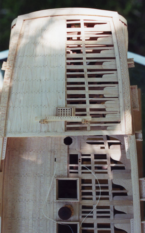
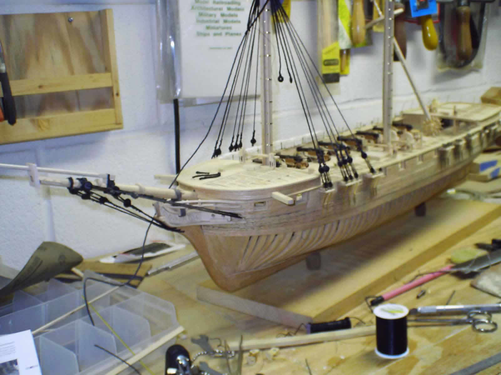
I did the framing in the conventional way, making up a custom building board, setting up the keel and stem/stern posts first, then erecting the frames individually using a framing jig to keep them plumb and square to the keel during assembly. The frames, deck and other timbers, masts and spars were made up of hard maple. Once the frames were up and secured with the keelson, I planked the hull in red oak, using wooden pegs to secure the planks as shown in the photos. As with the Essex model, I planked one side (starboard) fully, the other side only from the wales up, and planked the starboard half of the deck. I then added the timbering for the berth and gun decks, the various hatches and deck furniture and planked the starboard half of the decks. The picture below shows the hull after planking half the deck. A cannon is placed on the deck for size reference.
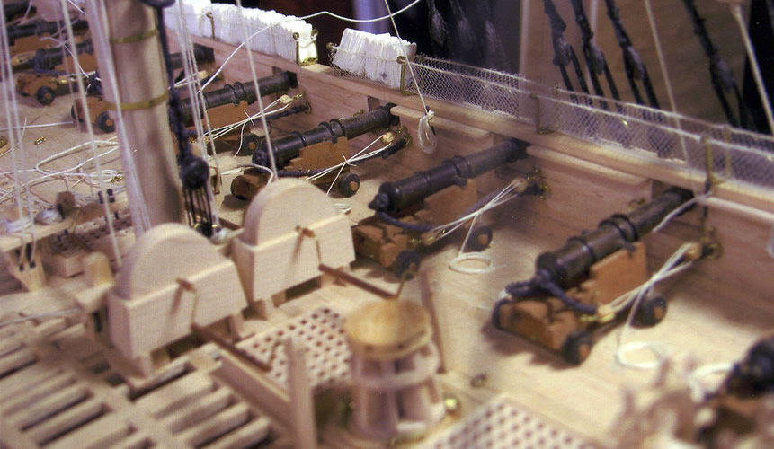
The picture below shows the hull after the cannon are mounted and the hammock nets fabricated and filled with hammocks.
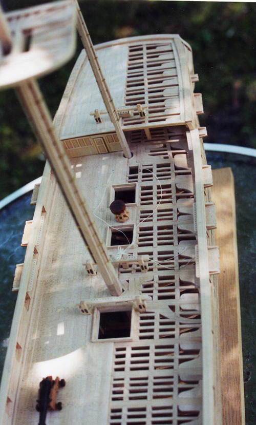
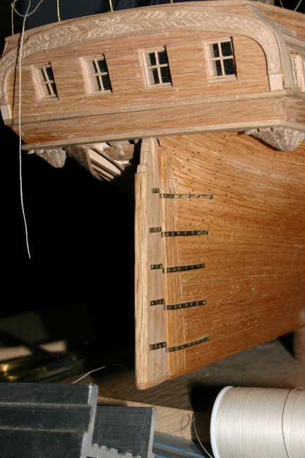
Here's a shot of the stern and transom after the hull is planked. Notice the fairly stright run of the planking without the "tuck" at the stern characteristic of earlier ships. On the unplanked port side, you can appreciate how far around the after cant frames come, almost all the way to the midline, making for a very short/narrow wing transom. You can also see how the wide transom has been stuck on this narrow span to add the quarter galleries on both sides. Other ships of this class probably lacked this feature.
Guns were turned from lignam vitae with carriages made of cherry and wheels of lignum vitae.
For details such as catheads, fife and pin rails, I turned up small sheaves of ebony and/or lignum
vitae and made up the timbers from thin strips of maple to enclose the sheave of each pully, with a
piece of brass wire for the shaft of the pully.
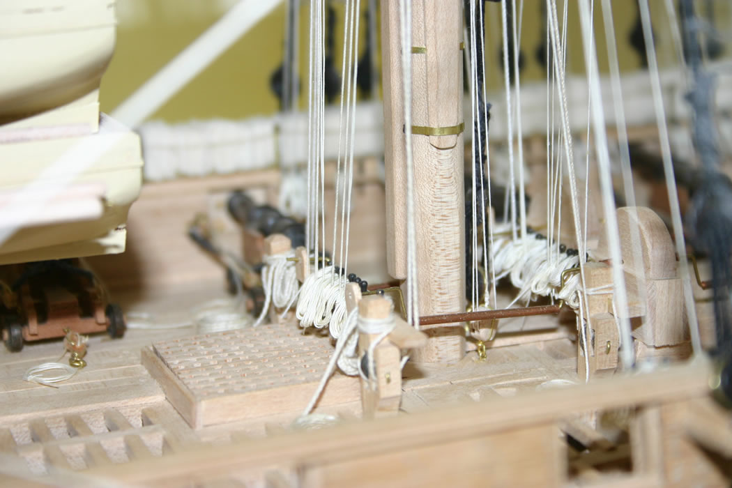
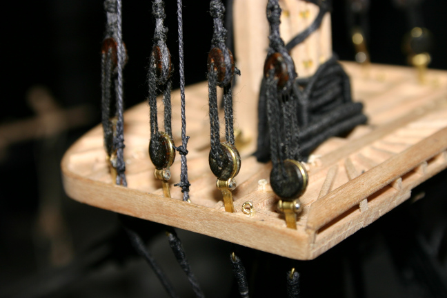
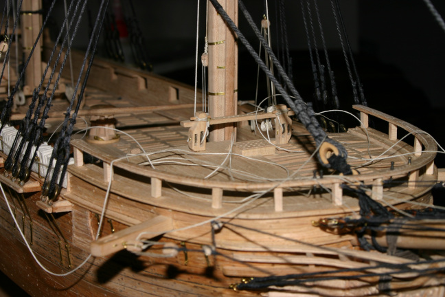
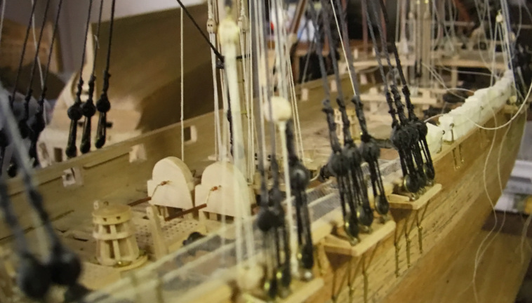
You can see some of this detail in this photo of the main pin rail on the finished model. You can
also see the built-up mast of maple with brass bands and the home made maple grating hatch cover.
While I was working on the hull of the Vandalia, I took some time to make up the cordage for the rigging. For details about making blocks, deadeyes, and other rigging items, information on how I made up the ropes and cables used in the model and description of the rope machine built and used for this purpose, check out the separate Ship Modeling in General page. That page also has a copy of the calculations I used to decide on the make up of the cordage, based on Steel's Elements rigging tables.
I rigged the model pretty much in the order that a prototype might have been rigged. That is, I began with the standing rigging for the bowsprit and lower masts working from fore to mizzen. I had fabricated the jib boom, topmasts and topgallant masts and the tops and made certain everything fit together and disassembled cleanly, but I did not assemble the entire masts before setting them. I set the lower masts, with tops, and rigged the shrouds and stays for each of them before installing the top masts for each. Once the top masts were in place and secured with a fid, I rigged the shrouds and stays for each topmast. I also have found it easier to set up the yards for the fore and main courses at this point. Later, once the topmasts are fully set up, I move on to the jib boom, the topgallant masts and the spanker boom and gaff. There is always some variation in the order in which I do things, based on how much a particular bit of standing rigging may affect access to parts of the masts needed for rigging the various yards.
This order of rigging the ship is sometimes a bit harder than pre-rigging each mast before setting it up, but it is a really good way to come to understand the function of the standing rigging and to get all the tensions balanced among the lines before adding the spars and the running rigging.
The photos below show progress in setting up the standing rigging.
First I set up shrouds and stays of bowsprit and foremast.
Photos below show the rigging further along. There are several pictures of the set up of the shrouds and stays over the foremast and some detail of the standing rigging at the foretop, the topmast stays.
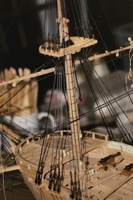
These pictures show the forecastle and the foremast with the standing rigging for the foremast set up and the yard for the fore course also set up, with the lines from the jeer blocks running through the sheaves in the fore topsail sheet bitts and the truss pendant blocks, with falls belayed at the pinrail on the main deck behind the mast.
Here's how things look when the standing rigging is pretty much complete. In the photo on the left, the fore topgallant stays are set up, but not the main or mizzen. In the photo on the right, the mizzen topgallant stays are set up and standing rigging is complete.
Below are some photos of the model with the running rigging in progress and after completion, with some comments and information about building techniques and the like.
On the left is a shot of the running rigging around the foremast. On the right is a photo of the rigging around the main mast pinrails. In the background of the right hand picture you can see the model of Raleigh. The Raleigh was built from the Harold Hahn plans using his method of upside down frame set up and planking. See builders notes on the Raleigh here.
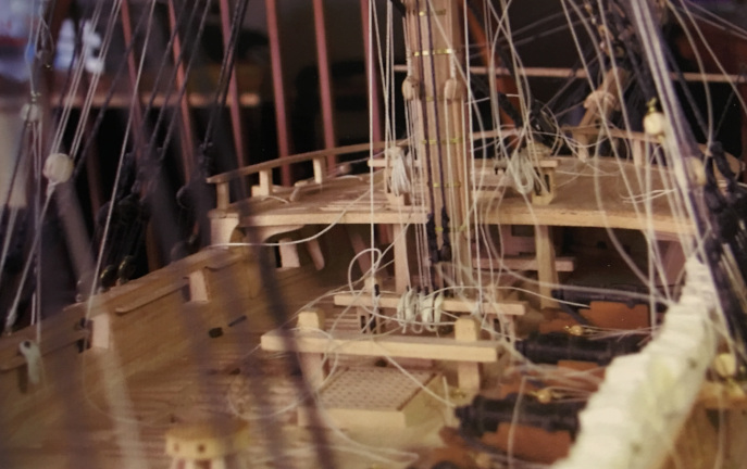
Some more in-progress photos, showing how gradually the apparent disorder of lines running everywhere comes together in a coherent manner.
Following are some photos of the finished model with a few comments.
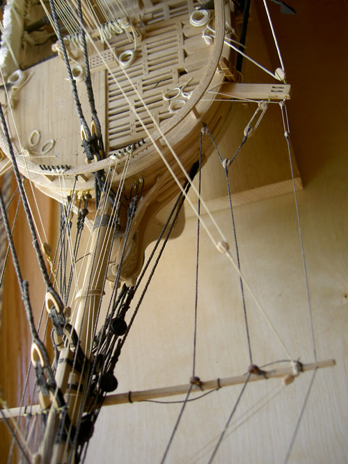
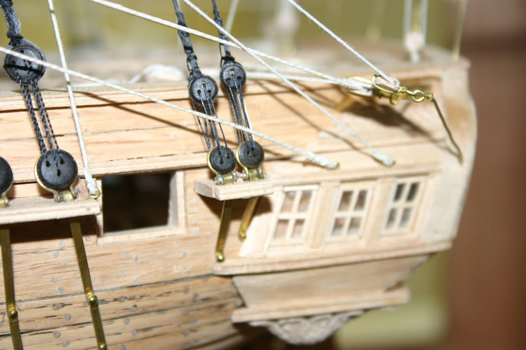
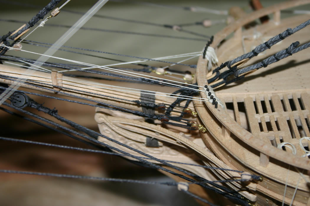
The bow with the portside anchor at the cathead. The anchor is made up of ebony for the iron part, cherry for the cross piece/stock, and brass bands around the stock. Also, the pully sheaves within the laminated cathead can be seen in this view. I only put in two sheaves, as to put in three, the proper number would have made the cathead too wide to look good.
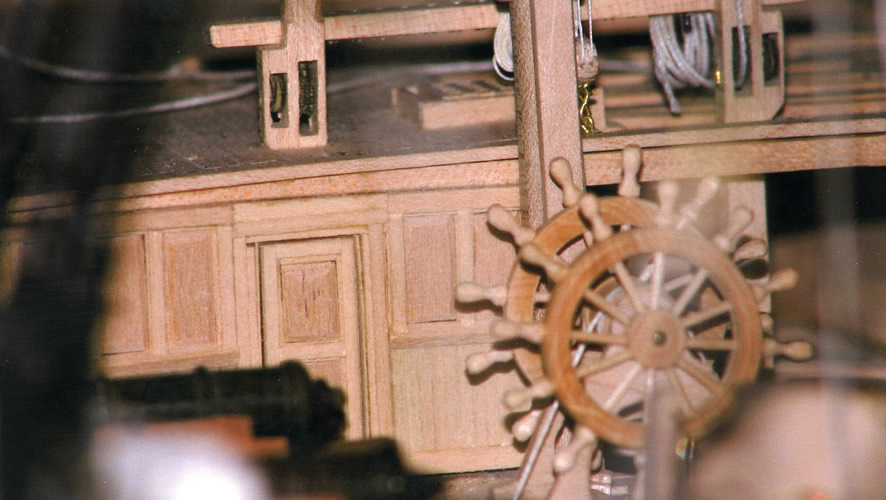
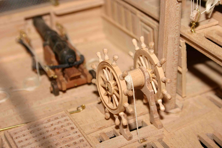
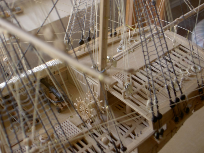
Views of the bulkhead at the front of the quarter deck and the ship's wheel in front of the bulkhead. The wheel rim was turned from boxwood and spokes made from toothpicks inserted into it with the outer ends of the spokes filed into hand grips. The hub of the wheel and the drum for the rope were also turned from boxwood.
On the quarter deck, the bitts and pin rails are visible and the sheaves in the bitts can be appreciated.
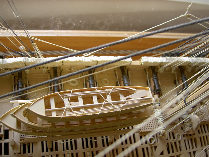
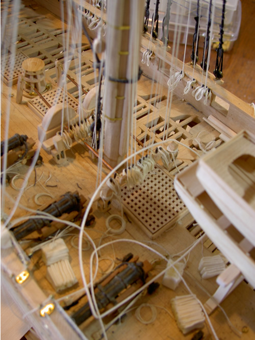
Views of the gun deck showing the ship's boats stowed in the waist and a more detailed pictue of the base of the main mast, the pumps, and a closer look at the cannon and the hammock netting and stowed hammocks.
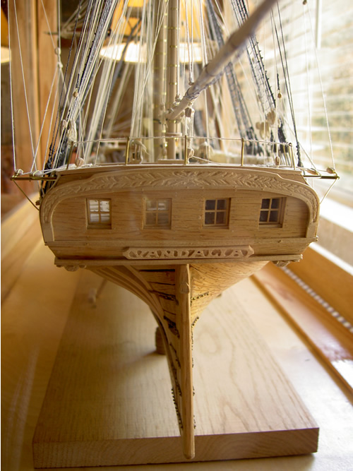
Above is a picture of the transom with its modest carving. Vandalia was constructed during the emerging era of "Jacksonian democracy" when ornate embellishment of ships, especially warships was out of fashion. The ship was without figurehead or elaborate carving anywhere other than the little seen here on the transom.
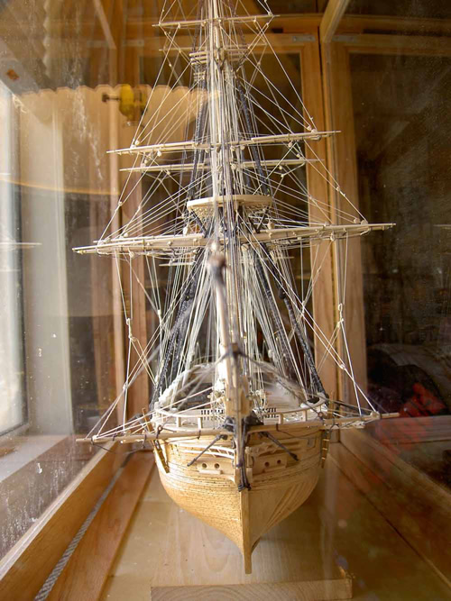
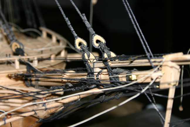
On the left is a photo of the model in case from the bow on. On the left is a picture of the head and the bowsprit. Another anacronistic rigging feature is shown in this shot. By the 1820s, the spritsail yard generally no longer carried a sail, but functioned only as a spreader for the lateral bow sprit supporting stays, which ran through thimbles fastened to the yard. For this model, in deference to the old-fashioned ideas of the first captain, I rigged the yard to carry a sail, which meant the bob stay had to run above the yard rather than below. A small point, but a fun bit of trivia. Since the entire rigging plan is conjectural, I felt I was free to do things as I felt without being entirely untrue to the period, or incorporating rigging equipment and techniques that had not yet been invented.
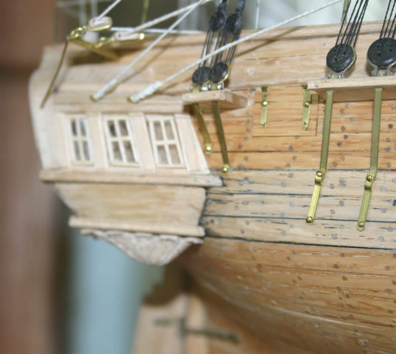
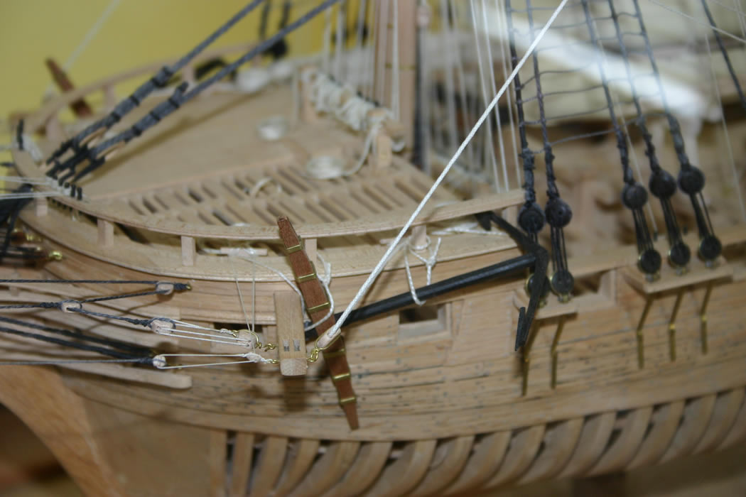
A view of the quarter deck on the completed model to the left, and on the right, a picture of the starboard side quarter gallery during hull construction to show the minimal embellishment and also show how the structure does look added on as an after thought.
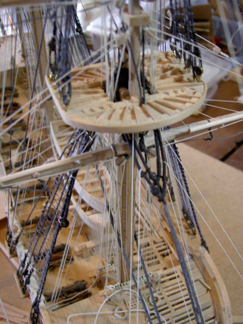
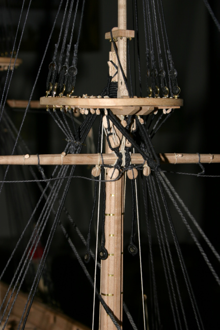
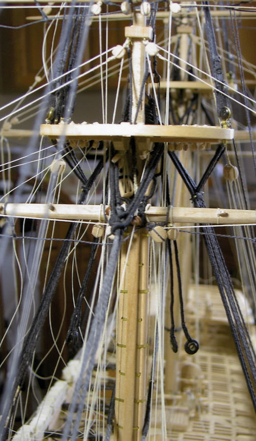
Two pictures of the foretop. On the left, rigging is nearly complete and on the right is the finished model. On both the fore and main top I rigged the blocks beneath the fore and after part of the top for the sail handling lines - buntline, clewline, etc.
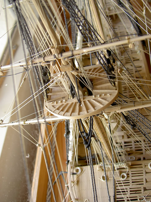
On the left is a picture of the main top before rigging the sail handling lines. you can see the small blocks fastened to the main sail yard and below the main top. On the left, the sail handling lines have been rigged and can be seen passing through the blocks on the yard and under the blocks on the forward part of the top. from there, the lines passed back to blocks fastened to the back part of the top and thence down to the pin rail to belay. Rigging these lines was a real painstaking task, as the blocks were very small, and were suspended from the top by a loop of line around the block which was held in place by a wooden peg on the upper side of the top planking.
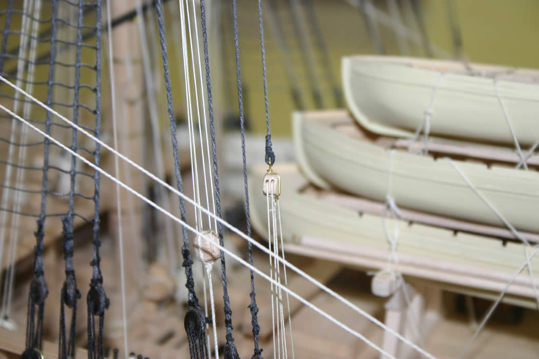
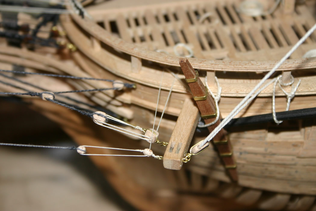
Some photos of the rigging on the model. On the left are the blocks and lines of the foretopsail halliards and the fore course sheets. On the right is a close up of the deadeyes of the mizzen mast just after setting up the shrouds. Deadeyes were turned of lignum vitae and blocks were carved from maple. The lines, rope and cable, were made up as described above.
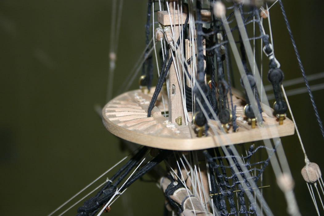
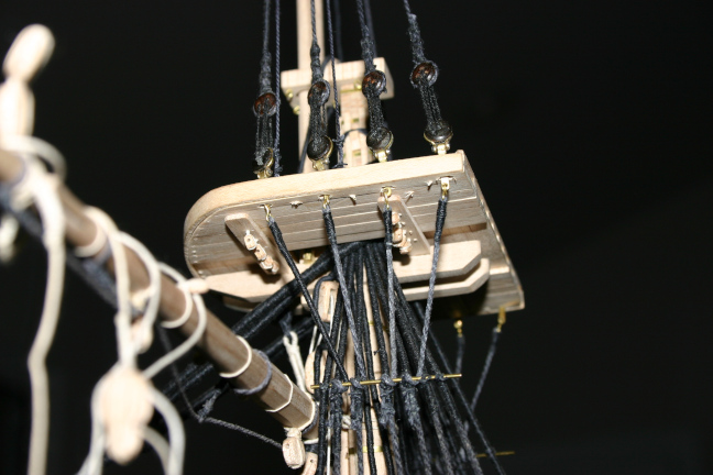
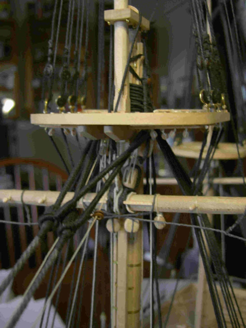
Some photos to show more detail. On the left is the foretop showing the bottom of the fore topmast with the sheave for the rigging to raise and lower the topmast and the fid holding the topmast upon the crosstrees, both the sheave and the fid are of brass.
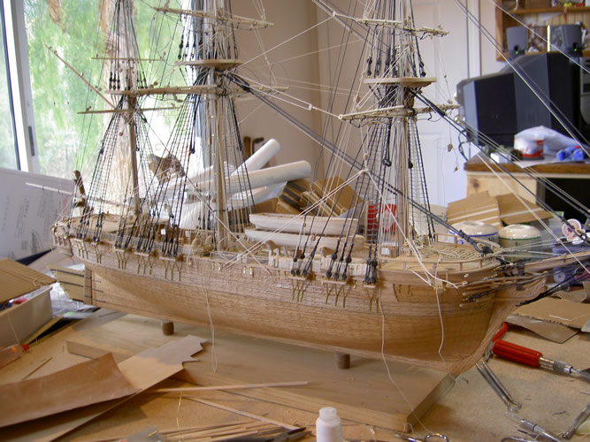
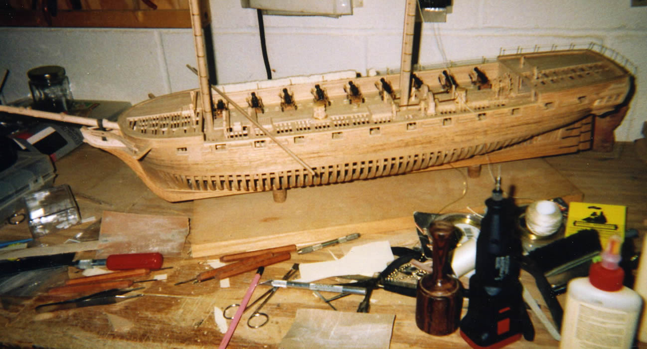
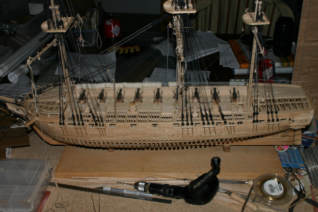
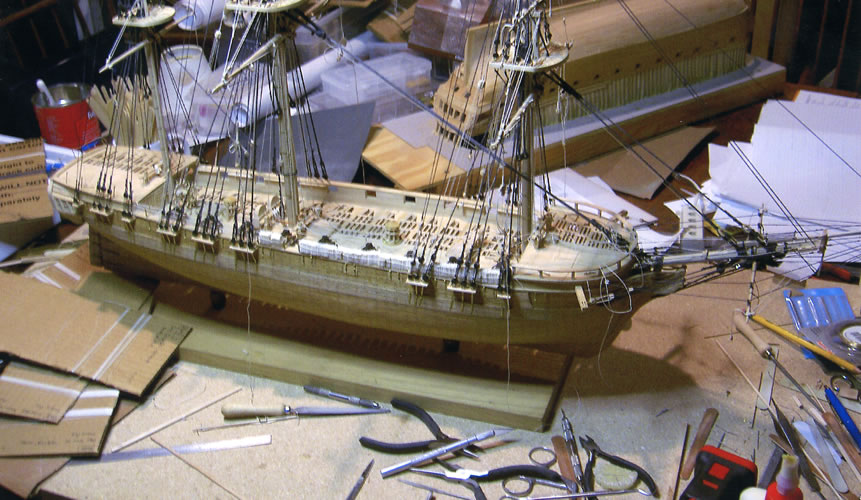
Vandalia on the workbench in California during final stages of rigging in 2004. Later that year, I showed the model at a ship model show on the Queen Mary. Still later that same year, we moved to Arkansas. And so did Vandalia.
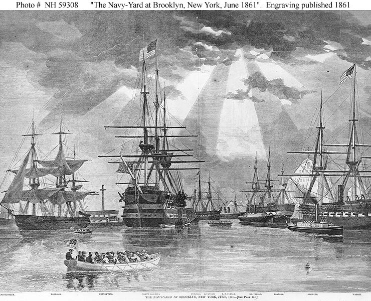
Below are some pictures of engravings of the later, rebuilt and rearmed, Vandalia during the Civil War. The first is an image of vandalia while participating in the blockade of Charleston, SC. and the second is an image of Vandalia (on the left)in the harbor of the New York Navy Yard, presumably at the end of 1861, at the end of her career.
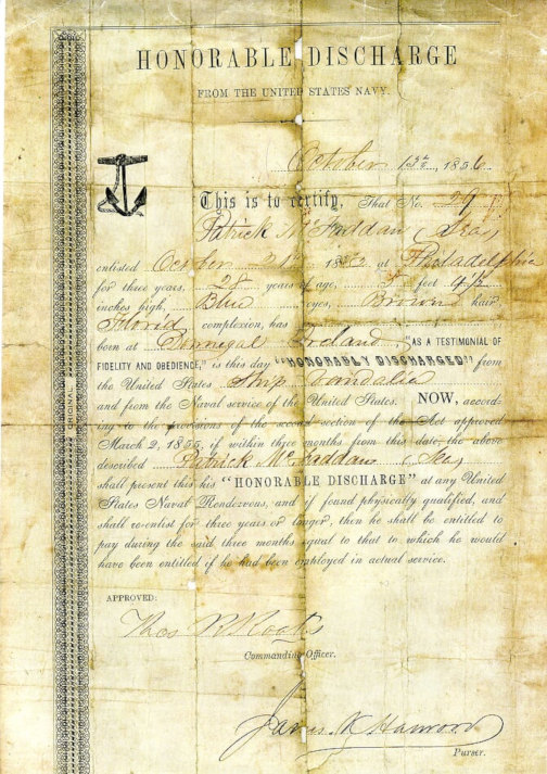
And below that is a photo of an honorable discharge certificate dated 1856 for Patrick McFadden, of Donegal Ireland, who served aboard the Vandalia, enlisting in 1855. This copy was provided me by a decendant of Patrick after viewing an earlier website posting about my model of the Vandalia.